
Uncategorized
-

August Spotlight: That’s a Wrap!
What’s the problem with missing torque specifications? What happens if outgoing power is separated into two conduits instead of the electrical code-specified single conduit? Why is my electrical panel partying without me?
Stay tuned in the coming weeks for the answers to these questions and more technical information, articles, and videos from experts and burgeoning actors at Control Concepts.
-

12 Costly Mistakes when Designing with SCR Power Controllers
Control Concepts’ experts can help you prevent and fix these mistakes. Review your design today to ensure it will run smoothly, reliably, and at peak performance.
Mistake 1. Incorrectly Sizing Your Controller
One of the most common design mistakes is improper controller sizing. While an undersized controller may experience excessive heat, reduced lifespan, component stress, or frequent failures, an oversized controller can lead to higher costs, reduced control resolution, and unnecessary system complexity.
Control Concepts flat rates controllers for the full frame current at 50˚C and 6000 ft. altitude. Consider the following requirements to improve both reliability and performance:
- Maximum current
- Ambient temperature
- Duty cycle requirements
- Safety margins
- Future needs
Mistake 2. Lacking a Mechanical Disconnect
SCRs are not mechanical disconnects and do not provide electrical isolation from the line voltage, even when off. Forgetting to include a mechanical disconnect may be fatal.
Mistake 3. No Electrostatic Shield in an Isolation Transformer with an Ungrounded Load
Without the electrostatic shield, AC current can couple across the transformer due to inter-winding capacitance. This results in measuring a potentially lethal secondary high voltage to earth ground.
Mistake 4. A Mechanical Contactor on the Load Side of the SCR
Customers often desire to switch loads using a mechanical contactor for safety or load trimming. When a mechanical contactor opens and closes, the contacts aren’t made simultaneously. If the contactor is opened under power, kickback voltages may be sent to the SCR, which can cause premature failure. Furthermore, when an SCR controller uses power or current feedback, the controller may momentarily apply full power to your load when the contactor is switched on, causing damage to the load, saturation of a downstream transformer, or blown fuses.
Mistake 5: Choosing the Wrong Firing Mode
SCR firing methods have varying trade-offs. Phase Angle Firing provides fast response and precise control at the cost of increasing harmonics, electrical noise, and power quality concerns. Zero Cross firing provides reduced harmonics, better power factor, and improved power quality. For many industrial heating applications, Zero Cross firing offers the best balance between performance and electrical efficiency.
To choose the right firing mode, consider the following design requirements:
- Load characteristics
- Process requirements
- Utility considerations
- Power quality objectives
Mistake 6: Poor Load Configuration Design
Load configuration directly impacts system performance, phase balance, efficiency, and operating costs. For example, unbalanced three phase loads cause uneven current distribution, while incorrect delta/wye selection may result in improper voltage delivery. Furthermore, load configuration design should account for future expansion.
Verify:
- Voltage requirements
- Load balance
- Power distribution strategy
Mistake 7: Missing Fuses
Protection devices like fuses are critical elements in the design because SCRs require rapid fault protection. Without proper protection, faults can destroy SCR modules and cause expensive fixes or lengthy downtime.
Mistake 8: Overlooking SCCR Requirements
Many facilities discover SCCR problems only during inspections or commissioning, leading to noncompliance, safety risks, and costly redesigns. To prevent this mistake, consider available fault current and the SCCR ratings of controllers and fuses during system design.
Mistake 9: Ignoring Thermal Management
Heat is the enemy of power electronics. Even properly sized SCR controllers can fail prematurely if thermal management is inadequate. Common thermal issues range from restricted airflow from poor enclosure layout to undersized cooling systems and elevated ambient temperatures. Warning signs to watch for: frequent alarms, unexpected shutdowns, or shortened controller life.
To best address this issue, consider cabinet ventilation, heat sink sizing, ambient conditions, and cooling requirements during the design phase.
Mistake 10: Missing Communication Requirements
Facilities increasingly require the following integration capabilities:
- EtherCAT
- Modbus TCP
- EtherNet/IP
- PROFINET
Plan communication architecture early in the project to improve visibility and system control, and to prevent costly redesigns.
Mistake 11: Poor Power Quality
Power quality problems can develop slowly and remain unnoticed for months. Common problems include harmonics, low power factor, and transformer heating. Learn more
Mistake 12: Designing for Today Instead of Tomorrow
The best SCR system designs balance current requirements with future possibilities, including increased production capacity, additional heating zones, new automation requirements, or different communications need. To prevent redesigns, retrofits, and downtime, consider how your needs may change in the future.
-
5 Costly Mistakes when Operating SCR Power Controllers
Control Concepts’ experts can help you prevent, diagnose, and fix these mistakes. Inspect your system today to keep it running smooth, reliably, and at peak performance.
Mistake 1. Not Fusing All Legs Feeding the SCR and Load
A short to ground can lead to a runaway load in single or three phase applications, possibly damaging expensive loads.
Mistake 2. Failure to Maintain a Minimum Load
An open load condition or a failure to meet a minimum current on the primary can cause the SCR to not commute (turn off) properly, which may eventually lead to saturation of the transformer and blown fuses.
Mistake 3. Operating Above or Below Rated Environmental Conditions
Many people believe running electronics in a colder environment is advantageous to the device. For SCRs, however, the required SCR drive current increases as the temperature decreases. This current increase can overtax the system and lead to misfires and potential saturation of downstream transformers. A small box heater is recommended for designs operating less than 32˚F / 0˚C. Operating the SCR controller above 50˚C shortens the life of the SCR and the associated electronic components.
Mistake 4. Dust in the Enclosure
Control Concepts strongly recommends using and regularly maintaining cabinet filters to reduce dust contamination of the electronics. Conductive dust inside the cabinet and on the controller will significantly shorten the life of the SCR and electronics.
Mistake 5. Neglecting to Test Possible Fault/Alarm Recovery Scenarios
Digital processors and communications have increased the number of possible fault conditions for modern SCRs. Control Concepts recommend methodical and systematic testing to test all possible alarms and fault conditions before a system is placed in production to reduce startup costs and scrapped product.
-

July Spotlight: Improve Power Factor with Zero Cross Transformer Mode
Phase Angle control has disadvantages – increased harmonics and decreased power factor. However, it is still the usual choice for system designers with isolation transformers in order to prevent transformer saturation.
Control Concepts offers a different solution: Zero Cross Transformer (ZCT) Mode. This firing mode is a cost-effective way to eliminate harmonics/power factor issues without compromising performance, quality, or reliability. ZCT Mode is commonly used in the field for excellent results.

Are you a good candidate for ZCT Mode?
- Do you want improved power factor?
- Do you use transformer-coupled loads?
- Do you have high thermal inertia OR require less stringent process control?
Visit Power Control University’s In Depth: Zero Cross Transformer Mode lesson to learn more, or contact our team of experts for help choosing the right firing mode for your application.
-
Sync-Guard, Trans-Guard, and Other Features
Control Concepts has pioneered several features for SCR power controllers to improve safety, reduce complexity, and allow greater visibility for monitoring and alarms.
Sync-Guard
Control Concepts created this feature to decrease the possibility of synchronous operation of two or more controllers. It reduces the variations in power demand, which results in a more stable supply voltage and improved power factor. Sync-Guard does not alter the power applied to the load, but adjusts the time when power is applied in such a manner as to reduce the possibility of the controllers being ON and OFF at the same time.
Trans-Guard
The use of Zero Cross controllers on the secondary of a transformer can cause saturation of the transformer, which results in excess transformer temperatures and early failure.
Transformers can be caused to saturate if a DC voltage is applied to the primary. DC voltage can be induced on the primary by DC components in the secondary. A simple half wave rectifier circuit will induce a DC voltage on the primary because the voltage drop across the source resistance (during the half cycle the diode conducts) will lower the primary voltage. The effect is the same as if a Zero Cross controller were not providing an equal number of positive and negative half cycles to the load. The source inductance can also cause a DC voltage to occur on the transformer primary.
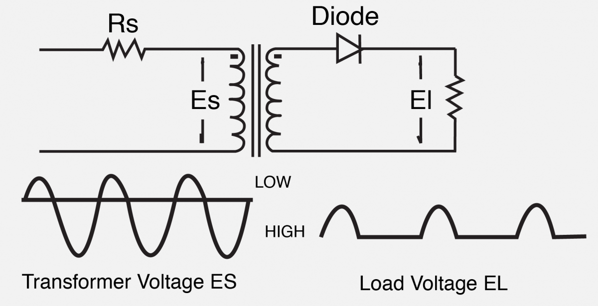
The Trans-Guard feature eliminates these problems by always supplying an odd number of ON half-cycles and an even number of OFF half-cycles. This technique guarantees that no DC voltage will occur independent of the source impedance or the load configuration.
The saturation problem is not likely to occur when the load is a small percentage of the transformer capacity, or when the source resistance and inductance are small. However, the potential problem always exists unless the controller is designed with Trans-Guard.
Soft Start & Missing Cycle Detection
These features are required in Phase Angle control to insure that the load power is gradually increased from zero to the value set by the command signal if load power is interrupted. This gradual increase of power prevents surge currents and avoids the possibility of saturating inductive loads like transformers.
Current Limiting
This feature, available only on Phase qngle controllers, prevents the load current from exceeding a preset value. Current limiting is used to protect the load, the SCR power controller, fuses, and the system supply from large surge currents that could occur at start up due to loads that have a low resistance when cold.
Feedback/Feed forward
Either feedback or feed forward provides the means to achieve a linear relation between the desired output and the control or command signal. Feedback implies that the desired parameter is measured and “fed back” to the input of the control such that the output can be increased or decreased if corrective action is required. Feed forward involves a less expensive technique in which the output is simulated in the circuitry and corrective action is taken based upon the simulated circuit response. Both techniques provide a linear output with respect to the control or command signals and eliminate the effects of load and supply variations.
Overcurrent Trip
The Overcurrent Trip feature prevents the SCRs from being turned on if the SCR current has exceeded a preset value during the last half cycle. This feature is an electronic fuse that eliminates the need for expensive and troublesome semiconductor fuses. The controller can be reset by either removing and re-applying power or by momentarily closing a remote switch. This feature has proven to be a more reliable protection technique than fast acting fuses.
Shorted SCR Detection
If an SCR does fail, it typically becomes shorted, allowing load current to flow continuously. In the event an SCR shorts, this feature energizes a relay which can be used to activate an alarm or remove system power.
Choosing the Right Features for Your Application
Depending on the application, these SCR power controller features may be critical elements in your system. Control Concepts has a team of experts on standby to help you choose the features you need to ensure safe, reliable power control for your system.